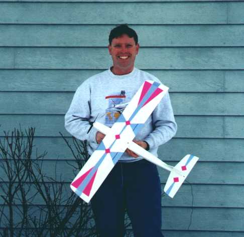
Sport 400
|
|
Stats:
30 inches
Wing Area: 180 sq in
Weight: 15 – 18 oz
Wing Loading: ~13 oz/sq ft
Power System: Speed 400 6v, 7 or 8 cell 500 mAh pack, 5.5x4.5 prop
Radio: Hitec 535 rcv’r without case, 2 HS 60 servos, JES 10C ESC
Power loading: ~90 watts/lb
|
Back in August 1997 I decided to enter the world of electric airplanes for the second time. The first time I tried a stock Stik-E from Hobby Shack, an old (found in the weeds) 6 cell pack, and a timed charger. Needless to say, the results were not encouraging. So when I decided to try electrics again, I took the approach of learning everything I could before choosing a plane. After lurking on the E-Flight list for several months, buying E-Calc, and reading many articles from the E-Zone archives, I felt I was ready to tackle electrics again. I was fascinated by the possibilities of Speed 400 planes and still did not want to invest too much money, so I decided to design a plane around this motor. I had previously designed a Quickie 500 racer, and since these are great flying airplanes, I used that design as the starting point. I opened up the CAD file for the Quickie and scaled it to 60%. The Sport 400 was born.
First flight was not an unqualified success. The plane flew well, but I ended up crashing because I did not have enough yaw stability. After checking the proportions I realized the rudder was ½ the size it needed to be. So it was back to the computer. I enlarged the rudder and, at the same time, enlarged the fuselage a little to make it easier to put the radio in. The first flight of the "Mk II" was a great success. I had a stable airplane that was fast and able to moderate aerobatics. It was also simple and inexpensive which makes it a great one-design plane for club races.
My two prototypes were constructed with contest grade balsa. Using good quality wood, you should have no problem coming in at a weight of 16 oz. My first plane was 16.5 oz (.5oz lead weight in the tail) and my second plane was 15.1 oz.
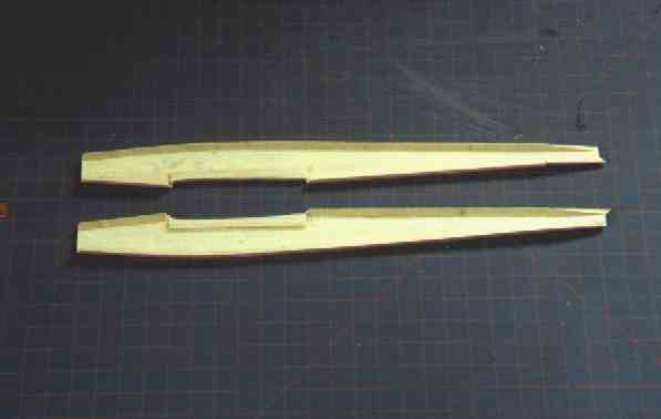
FUSELAGE
- Start construction by cutting out the fuselage sides and formers. Both sides can be cut from one sheet of 1/8" x 3" x 36" balsa. The motor mount is a cut down square Speed 400 mount available from Tim McDonough.
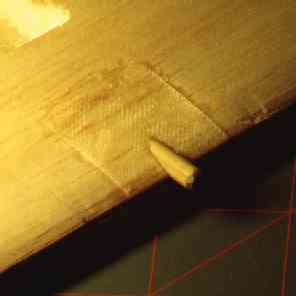
- Add the ¼" triangle to the edges of the fuselage sides. Make sure you make both a left and right side. Also note the triangle stops 1/16" short of the front edge for the firewall, and 1/8" short of the back of the wing saddle for the F3 former, and 1/8" short of the front of the wing saddle for F2A. I can never seem to find light triangle stock at the hobby store, so I make my own from light ¼" sheet. Take a balsa stripper and make a ¼" x ¼" stick, then use a razor plane to remove material from one side and make a triangle.
- Add the doublers for the wing saddles.
- Bevel the triangle at the rear of the fuselage so the sides can be joined together.
- To make absolutely sure your sides are identical, pin them back to back and sand the edges even. Keep your sanding block at a 90 degree angle. Taking this extra step ensures your scratch built plane is perfectly straight.
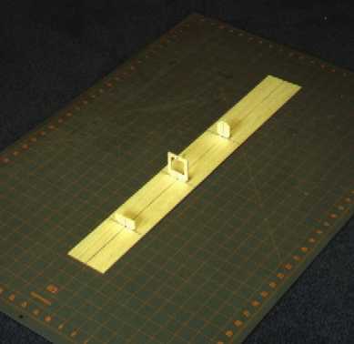
- Take a piece of 1/8" balsa sheet and draw a line lengthwise down the center. Draw lines at 4 1/4", 10 3/8", and 17 1/4" for the locations of the formers.
- Draw a vertical center line on the formers and the firewall.
- Glue the formers on the fuselage bottom using the centerlines to line them up. Note that F2B will be removed later, so just tack glue it.
- Now add the fuselage sides, first gluing them to F3. Do not glue the sides to the bottom at this time.
- Keeping the sides pressed to the bottom, bring them together in the back and glue them to F4. Again, don’t glue them to the bottom yet.
- Join the sides at the tail and glue together.
- Now glue the back down to the bottom, making sure it is centered on the line.
- Continue gluing the sides to the bottom, up to F3, pressing down to get a good bond.
- Roll the sides forward on the bottom so that the sides between F3 and F2B touch the bottom. Glue sides to F2B.
- Glue the firewall between the two sides.
- Roll the sides forward again and glue the firewall to the bottom, making sure to line up the center lines.
- Glue the rest of the sides to the bottom.
- Trim the bottom sheet flush with the fuselage sides.
- Add the wing dowel holder F2A and remove F2B.
- Add the rear wing hold down block.
- Sheet the top back of the fuselage with 1/16" cross-grain balsa and trim flush. Leave the front top sheeting off for now.
- Go on to the wing section and return here once you have drilled the wing for the hold down dowel.
- Sheet the top front of the fuselage with 1/16" cross-grain balsa and trim flush.
- Sand the corners of the fuselage round.
- I reinforce the front of the fuselage with glass cloth, but this step is optional. Using ¾ oz glass cloth and epoxy, cover the fuselage from the firewall to 1" beyond the opening for the wing. Check out Jim Ryan’s article on doing this without adding a lot of weight. This added 4 grams to the weight of my second prototype. The fuselage is essentially complete at this point.
WING
- First decide if you want the thick 3/4" wing or the standard (RG14) wing.
- Start by cutting out the foam cores and sheeting them with 1/32" balsa. The wing is sheeted in one piece with no dihedral.
- Add the leading edge and sand to shape.
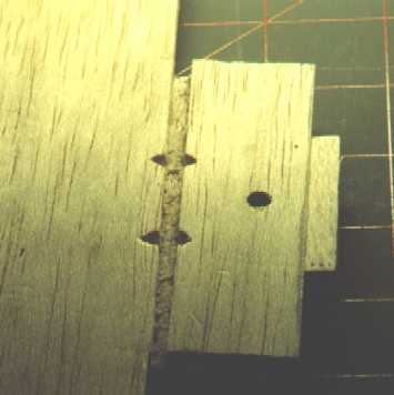
- Insert the dowel support piece, W1 in the wing.
- Put your wing on the fuselage and get it aligned with the fuselage. Measure from a point in the middle of the tail section to equal points out on the wing. Make sure they are the same distance then pin the wing to the fuselage.
- Use a long 3/16" drill or a Dremel with a 90 degree attachment to drill through the front of F2A into the wing for the dowel.
- Trial fit the dowel and the wing to the fuselage.
- If every thing is OK, pull out the dowel and reinforce the leading edge at the dowel location by wrapping some 1" wide fiberglass tape from wing top to wing bottom.
- Trim the cloth where it covers the dowel hole.
- Glue the dowel in place.
- Put the wing back on the fuselage and make sure it is aligned again. Drill through the wing into the rear hold down block with a #25 drill.
- Take the wing off and enlarge the hole to 3/16".
- Tap the hold down block with a 10-32 tap. Harden hole with thin CA.
- Remount the wing and install the fairings at the leading and trailing edges, sand to shape. To line up the rear fairing, you will need to mark the position on the wing, then take the hold down bolt out before you glue on the fairing. Once glued, use pins to hold the wing in place and match sand it to the fuselage. Once the fairing is shaped you can extend the hole for the bolt by drilling from the bottom of the wing.
- Cut out the ailerons as shown on the plans and face them with 1/8" balsa.
- Face the cut outs in the wing core with 1/16" balsa.
- Make a groove for the torque rods and install them.
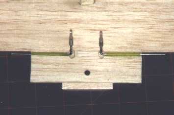
- Make a cutout for the servo and set up your linkage.
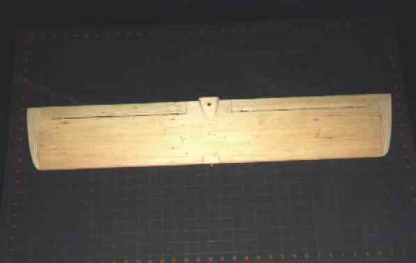
- Add the wing tips, hinge the ailerons, and cover.
- Finished wing:
EMPANAGE
- Cut out the rudder and stabilizer.
- Sand the edges round.
- Mount the wing on the fuselage. Glue the stabilizer on, making sure it lines up with the wing. The wing and the horizontal stabilizer are both at 0° incidence.
- Glue the rudder on, using a 90 degree triangle.
- I actually prefer to cover the fuselage, rudder and stabilizer before gluing them together, but either way works. I recommend using tape or covering to hinge the elevator.
FLYING
Cover the plane and install your radio, then balance the plane. Set your elevator throw to +- 1/4" and your ailerons to +- 1/4".
With a firm hand launch the plane should leap into the air. The plane flies fast but it is very stable. Stalls are gentle with no tendency to tip stall. Large loops from level flight are no problem so mild acrobatics are possible. I hope you enjoy flying this airplane as much as I do.